I have been dabbling in the ‘Internet of Things’ for a while and have finally decided to monitor some ‘things’ around home. I looked around at several off the shelf items as well as a few DIY type offerings (i.e. Open Energy Monitor) but found them to be to exclusive, to expensive, to power hungry, to big or just not quite right. As I want to monitor lots of things (not sure what yet, but have lots of ideas) cost is important and so decided to do my own DIY job!
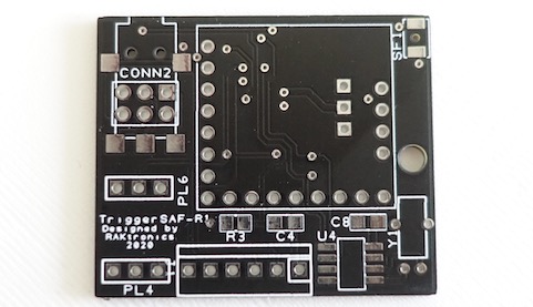
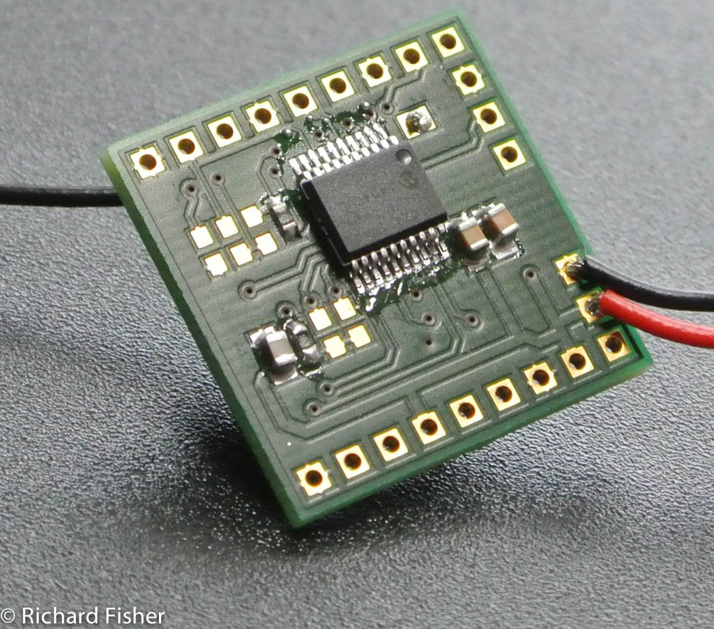
I like what the open energy monitor (OEM) team have done so decided to base my design on their system so they could one day talk to each other. Once I have something running the plan is to make it available for everyone to use. I have used a RFM12B transceiver module, this will allow two way communications so the monitors could ultimately become controllers as well. After much research, design and prototyping I discovered that this module is no longer manufactured, but luckily have found a 100% compatible part – whew! Unlike the OEM team I decided to go down the microchip PIC route as I have used these in the past and know the product and toolsets well. The board also has a row of pins that the PICKIT2/3 can be connected directly to. I settled on one of their nanowatt parts to get the best battery life I can, with a reasonable update speed I hope to get at least one year from a single CR2032 cell, only time will tell! Once again it is the external connectors that dictate the size of the final board. I wanted to make all unused pins available and to put them on a 0.1″ pitch so the board could be piggy-backed on to a standard veto board. The final size of the board is 24mm*24mm so not to bad.
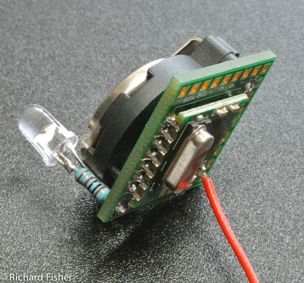
Final specification:
- RFM12B RF module.
- PIC24F16KA101 MCU from microchip.
- Low standby power (<1uA).
- Four analogue/digital inputs one of which is an interrupt source.
- I2C interface.
- Switched sensor power.
- Analogue voltage reference.
- Standard PicKit programmer interface.
- Voltage range 2.2-3.3V. Power from a double AA/AAA or single Lithium cell.
- 24mm*24mm size.

I have a number of modules sending dummy data to a central receiver, all seems to work OK. Whats next?
- To decide on some basic sensors and get them working, calibrated and sending the data to the receiver.
- To modify the receiver to error check the received data and send it to a PC based data logger.
- To be able display some graphs on a PC to show trends.
- To design and build a stand alone receiver and data logger and web server.
Watch this space for more info….

