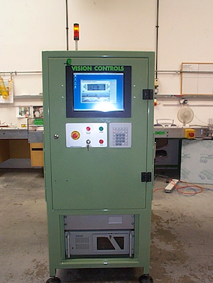
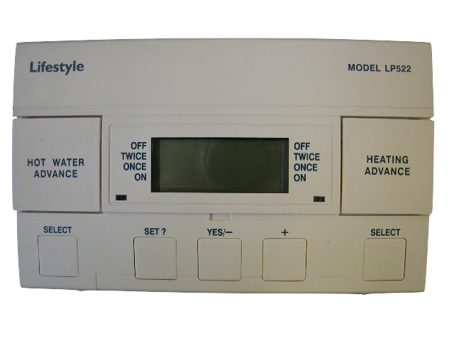
The requirements:
- 100% Accurate, no false passes, very low false fails.
- Fast, quicker than by hand.
- Minimum change over between batches.
- Rejects to be isolated and a fault report printed.
- Minimum user input.
- Test for cosmetic damage.
- Fully test the display.
- Full electrical test.
What we came up with:
- A very accurate system, can’t remember the exact results but we did exceed expectations.
- Unsure of actual speed but was substantially faster than by hand.
- The timers had to be loaded and unloaded by hand, but apart from that and selecting the timer under test it it all automatic.
- All the reject timers are pushed down a locked and covered chute and a ticket printed.
- Each timer was taught and a script written for the individual tests. The number of these was only limited by the hard disk capacity.
How the system works:
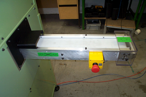
The timers are loaded on to the input conveyor, make sure they are the correct way around (they will automatically be rejected if they are).
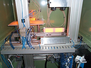
The timers are then automatically feed in to the systems and the two inspection areas.
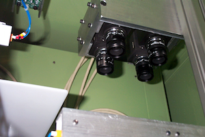
The first inspection area check makes sure the timer have been loaded correctly and then proceeds to perform a cosmetic check.The cosmetic check makes sure we have the correct model by looking at the part number and the providers logo. It then check all of the surfaces for print quality and any blemishes. If any of these fail the functional check is skipped and the timer is placed into the rejection chute.
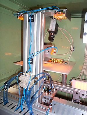
Assuming the timer passes the cosmetic check the timer then passes to the functional check area.The meter is first held in place from above by the plunger plate that is lowered using a pneumatic cylinder.Once this is in place a second pneumatic cylinder below the timer raises a contact block on to the electrical contacts on the rear of the timer. This provides power for the timer and monitors the outputs from the heating and water relay contacts.
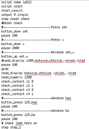
A script is loaded from the hard disk. This script is unique to each style of meter and contains a list of instructions to test the individual timers.
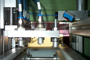
A set of pneumatically controlled plungers press the buttons on the timer in accordance with the script.
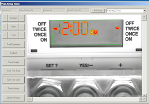
At each stage the display is read and the voltages and the voltages on the contacts measured, all controlled by the script.
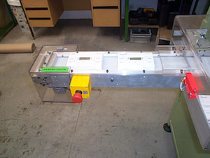
If the timer passes all the tests it is placed on to the output conveyor.
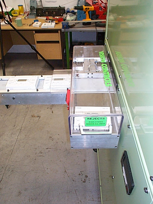
If the timer fails any of the tests it is placed into the output chute and a fail ticket is printed by a small printer in the side of the machine.If either the output of reject chute gets full the system automatically stops and a warning traffic light on the top of the system flashes.
Construction details
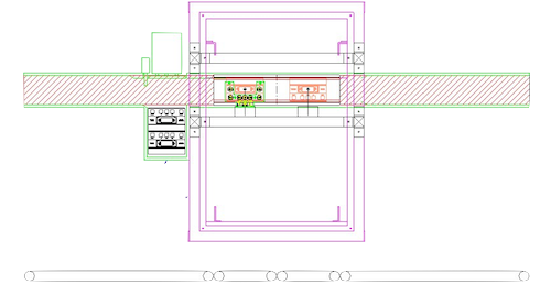
The top down drawing of the system.
Note the four conveyor sections in the detail below.
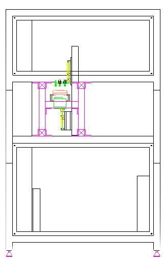
The drawing of the system from the side.
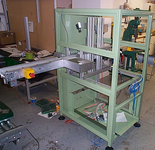
The base frame and conveyor.
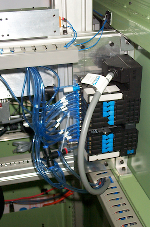
The pneumatic valve block.
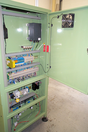
The open rear.
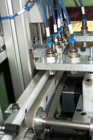
The functional test area.
Videos
The input and output conveyors
The tests
Finished system

Front of the system
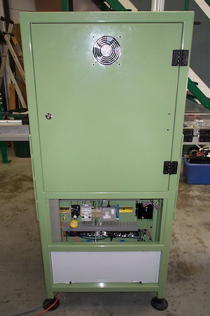
Rear of the system (panel removed).
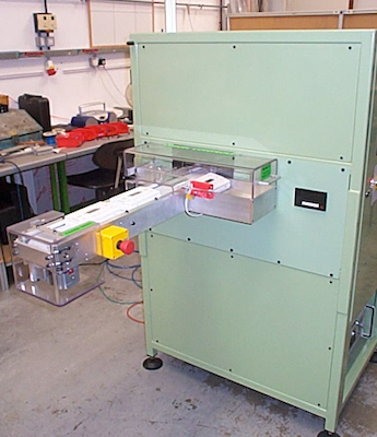
Left (output) area.
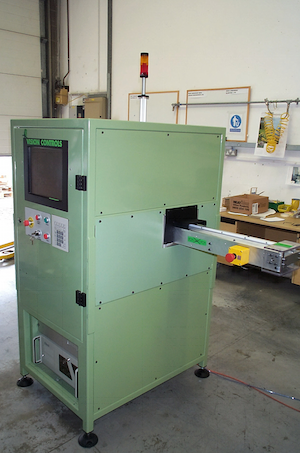
Right (input) area.
My part in the project
This was one of my projects so I…
- Project managed.
- Liaised with the client.
- The mechanical design.
- The electrical design.
- The electronics design.
- Pneumatic design.
- Some of the build.
- The software.
- Testing.
- On site installation.
- On site commissioning.
- On site training.


