This is another system I was very pleased with. It ran fast very efficiently (not without it’s teething problems!), the customer was so pleased with it he ordered several more. All of the software was written in visual ‘C’ and used multi-threading for various sub sections of the application notably the PLC, image processing and user interface.
The company was Pico electronics.
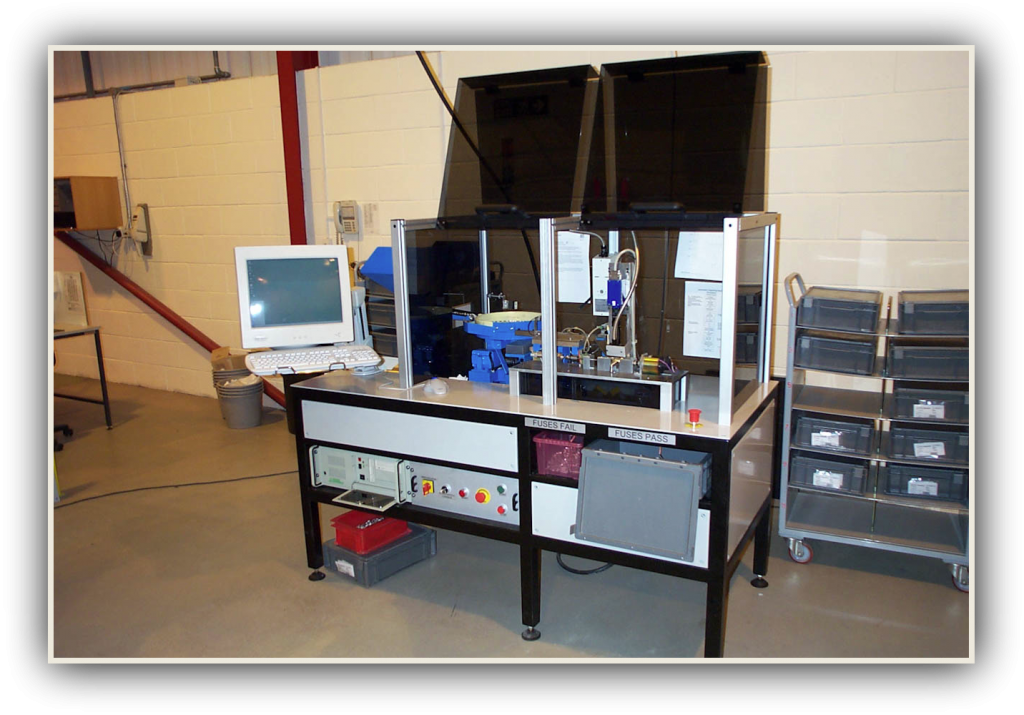
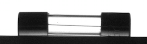
We had an enquiry from a company that added value by inspecting fuses. The fuses where brought in and needed to be tested for continuity and the identification marking.
The continuity check was already in hand, what the company needed was a way to read the ratings on one end of the fuse and the safety markings on the other.
The requirements:
100% Accurate, no false passes, very low false fails.
Fast, sub 1 second.
Minimum change over between batches.
All passed and failed fuses to be counted to verify.
Minimum user input.
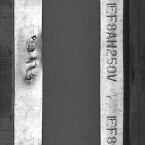
Verify the voltage and current rating from one end cap.
Verify the safety makings on the other end cap.
What we came up with:
A very accurate system, can’t remember the exact results but we did exceed expectations.
A 600ms test time per fuse, almost twice the required speed.
Apart from manually loading and unloading the fuses the only interaction was to select the correct test on the test software and press the go button.
All fuses going down the pass and fail chutes are counted.
After some fine tuning on the design very little user interaction was required. The system was self monitoring and a traffic light indicator warned the operator of any snags, this way a single operator could manages several machines.
The system was so successful that we ended up building several more for the company.
How the system works:
A set of three vibratory feeders feed the fuses in to the system.
The fuses are first loaded in to a bulk hopper, these are then trickle fed into a rotary bowl feeder, this is controlled by the computer to maintain a constant level in the rotary bowl. The fuses pass from the rotary bowl into the linear section. The final linear feeder creates a steady controllable feed of fuses in to the system.
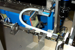
Linear to feeder tube via pneumatic actuator.
Down through tube into inspection area.
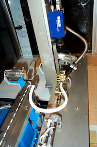
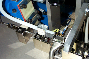
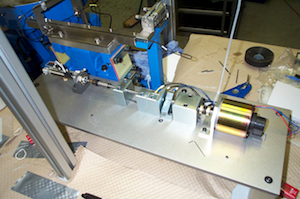
The fuse is clamped between two rotating shafts and rotated under a line scan camera, this has the effect of flattening the fuse.
The optical character recognition finds the relevant text and symbols on the ends of the fuse, it is then compared against the expected result and a pass fail decision is made.
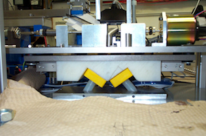
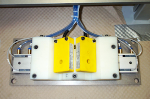
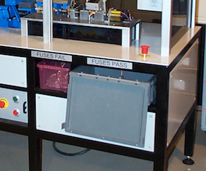
The fuse drops into a small holding area until the pass fail decision is made, one of a pair of sliders then opens to allow the fuse to fall into either the pass of fail bin below.
The yellow devices in the picture are the inductive counters that verify that the fuse has dropped down the correct chute.
The pass and fail bin. Any attempt to remove these while the system is running halts the test and invalidates any results.
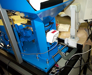
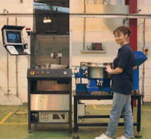
An overview of the complete testing mechanism part way through the build.
My part in the project:
Project managed.
Liaised with the client.
The mechanical design.
The electrical design.
The electronics design.
Pneumatics.
Prototype assembly.
PCB design and build.
The software.
We also sold the company one of our Checkfast systems to check the integrity of the wire inside the fuse (not the continuity).
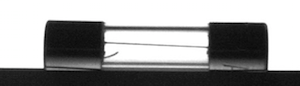
The top image shows a good fuse, the lower fuse may fail due to the small wisp of wire on the lower left. Other fails would include no wire or a broken wire.